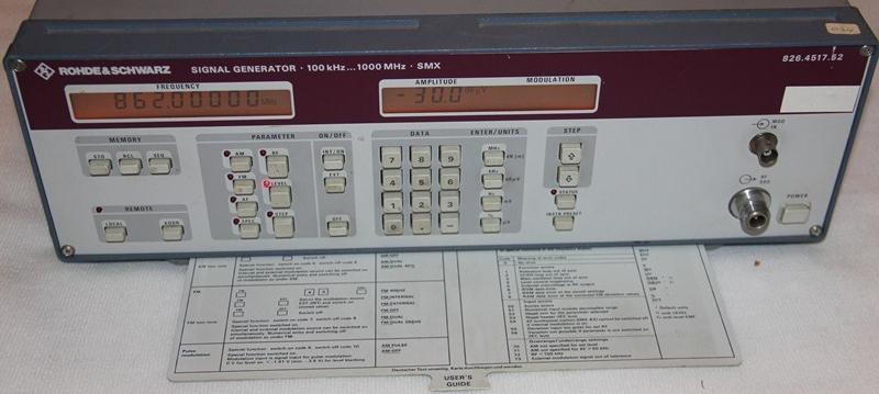
This generator from Rohde & Schwarz works from 100Khz at 1GHz. The generation of signals is made by three VCO whose operating ranges are nested into each other over the entire operating range of the equipment.
This is a trick for the generation of RF signals over a wide operating range but it slightly complicates the repair of a classic failure of this device : the loss of lock on one or more PLL that drive the three VCO.
I had to readjust these VCO twice in 5 years. Indeed, the VCO drift with use to a point where the PLL is no long able to hang. At this time, the generator reports an lock error and does not generate anything (or in some cases a free signal on a different frequency that the one set on the front panel).
To resolve this problem, this is how I did it :
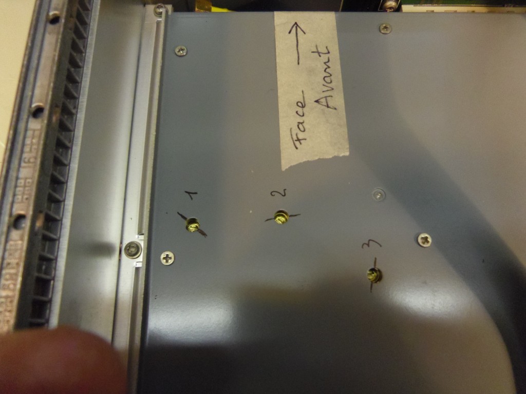
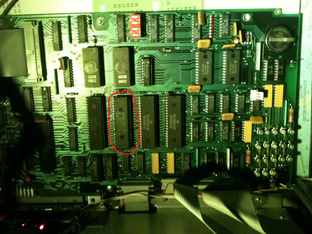
Remove the cover of the unit and return it to see the photo below:
Note the position of the three VCO as I did then remove the cover of this block.
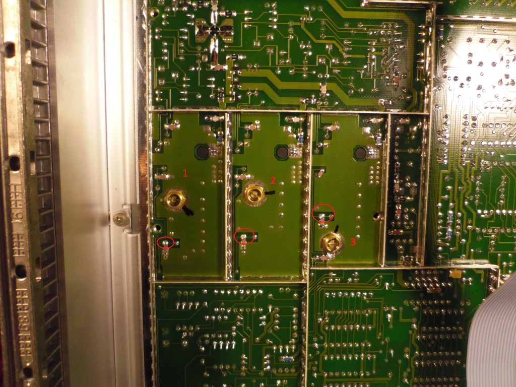
Set the generator to the 25.00001 MHz on the front panel and adjust the VCO1’s capacity to measure a voltage of about 3V on the point surrounded of VCO1.
Then set the generator on 40.945690 MHz and check that the voltage at the point of measurement is approximately 18V.
Do the same for the setting of VCO2 in use 40.9457 MHz for the minimum and 51.56 MHz to the maximum frequency of the generator’s front panel value.
Do the same for the setting of VCO3 in use 51,57 MHz for the minimum and 62 MHz to the maximum frequency of the generator’s front panel value.
In doing so, we get a few years of operation with a good signal generation across the range of use of SMX.
J’ai fait l’acquisition d’un milliwattmètre HP438A en panne, comme à mon habitude, pour équiper mon labo.
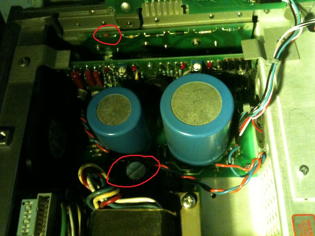
Quand je l’ai reçu, la première panne constatée était le -15V qui était défaillant et présentait une tension alternative d’une vingtaine de volt d’amplitude. En cause, deux condensateurs qui ont mal vieillis :
L’un est en parallèle de CR3 (C1 ou C2) sur la carte A8 (celle avec les composants sur dissipateur).
L’autre sert à la régulation du -15V : C3 d’une valeur de 680µF sur A10 (le fond de panier de l’alimentation).
Malgré cette première réparation, le milliwattmètre a changé d’état mais était toujours en défaut. En effet, il passait des erreurs “No Channel”, “2 inputs”, “input OL”, “please 0” en permanence et de manière totalement aléatoire, avec ou sans sonde. Voici une description vidéo de cette panne :
Au début j’ai pensé à un problème sur l’étage analogique mais après plusieurs semaines d’investigation, toutes les analyses menées sur cette partie en suivant le service manual n’ont rien donné.
Puis en mettant l’appareil en mode calibration A/D (switch S1 sur 0000), je me suis rendu compte qu’il était possible de mettre les switchs analogiques et multiplexeurs internes dans un état où je pouvais tester le bon fonctionnement du convertisseur A/D. Or, une fois démarré dans cet état, l’appareil continuait à afficher des valeurs incohérentes (0 ou -35125 de manière totalement aléatoire). Avec l’aide de Philippe, F1ETA, nous avons effectué une comparaison des signaux sur l’ensemble de la chaîne de conversion A/D mais tout semblait conforme. La partie analogique du convertisseur semblant correcte, il ne restait “que” la partie logique. D’après le schéma, hormis un porte logique et une bascule JK qui semblait fonctionner correctement, il ne restait que le timer qui sert au comptage du temps de comparaison du convertisseur. Par chance, LittleDiode sur Ebay en avait que j’ai donc commandé. Après échange, l’appareil a repris un fonctionnement normal.
The author declines any responsibility related to the use of informations and documents that may be made by its readers.
The contents are broadcast here for information purposes only and may contain errors. If the reader finds errors, he can in no case worry the author, but could report him to make the necessary corrections for future readers. Privacy Policy Cookies Policy
Solar-Terrestrial Data
Google
Send email
Gérer le consentement aux cookies
Nous utilisons des technologies telles que les cookies pour stocker et/ou accéder aux informations relatives aux appareils. Nous le faisons pour améliorer l’expérience de navigation et pour afficher des publicités (non-)personnalisées. Consentir à ces technologies nous autorisera à traiter des données telles que le comportement de navigation ou les ID uniques sur ce site. Le fait de ne pas consentir ou de retirer son consentement peut avoir un effet négatif sur certaines fonctonnalités et caractéristiques.
Fonctionnel
Always active
Le stockage ou l’accès technique est strictement nécessaire dans la finalité d’intérêt légitime de permettre l’utilisation d’un service spécifique explicitement demandé par l’abonné ou l’internaute, ou dans le seul but d’effectuer la transmission d’une communication sur un réseau de communications électroniques.
Préférences
Le stockage ou l’accès technique est nécessaire dans la finalité d’intérêt légitime de stocker des préférences qui ne sont pas demandées par l’abonné ou la personne utilisant le service.
Statistiques
The technical storage or access that is used exclusively for statistical purposes.Le stockage ou l’accès technique qui est utilisé exclusivement dans des finalités statistiques anonymes. En l’absence d’une assignation à comparaître, d’une conformité volontaire de la part de votre fournisseur d’accès à internet ou d’enregistrements supplémentaires provenant d’une tierce partie, les informations stockées ou extraites à cette seule fin ne peuvent généralement pas être utilisées pour vous identifier.
Marketing
Le stockage ou l’accès technique est nécessaire pour créer des profils d’internautes afin d’envoyer des publicités, ou pour suivre l’internaute sur un site web ou sur plusieurs sites web ayant des finalités marketing similaires.

 Français