Numeric

Radio

Electronic

Library

Software

Privacy Policy

Politique de cookies (UE)

MCU ST

Radio

Electronic

Library

Software

Privacy Policy

Politique de cookies (UE)

Afficheur GPS V2

Sorry, this entry is only available in Français.

Afficheur GPS NMEA

Radio

Electronic

Library

Software

Privacy Policy

Politique de cookies (UE)

Afficheur GPS NMEA V1

Description

Ce montage permet d’afficher certains paramètres contenues dans des trames NMEA issues d’un GPS sur un afficheur LCD graphique de taille 122×32 pixels. Les paramètres qui y sont affichés sont les suivants :

  • Date et heure UTC.
  • Longitude, latitude, altitude.
  • Nombre de satellites reçus, DOP.
  • Déclinaison magnétique.

Le montage est basé sur un PIC18F2620 qui reçoit les trames NMEA sur un port UART et affiche leur contenu sur un écran LCD graphique de 122×32 pixels piloté par un protocole compatible avec les contrôleurs graphiques SED1520. Les trames NMEA doivent être au débit de 4800 bauds.

Il n’y a pas de dessin de circuit imprimé fourni pour ce montage car je l’avais réalisé sur une plaquette à trous. Le code source est écrit pour le compilateur C18 de Microchip.
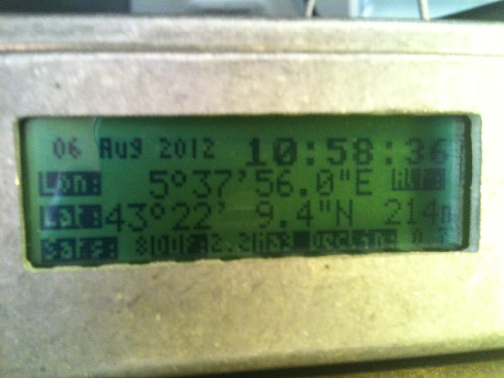
Photos

Schémas et routages Cadsoft EAGLE

afficheur_NMEA_GPS - SCH
Title: afficheur_NMEA_GPS - SCH (2431 clicks)
Caption:
Filename: afficheur_nmea_gps-sch.rar
Size: 63 KB

Schéma

afficheur_NMEA_GPS - SCH
Title: afficheur_NMEA_GPS - SCH (2431 clicks)
Caption:
Filename: afficheur_nmea_gps-sch.rar
Size: 63 KB

Code source et HEX

10mhz_gps_HEX
Title: 10mhz_gps_HEX (1901 clicks)
Caption:
Filename: 10mhz_gps_hex.rar
Size: 16 KB
Afficheur_NMEA_GPS - source
Title: Afficheur_NMEA_GPS - source (1912 clicks)
Caption:
Filename: afficheur_nmea_gps-source.rar
Size: 17 KB

F4CTZTracker

Radio

Electronic

Library

Software

Privacy Policy

Politique de cookies (UE)

Microchip DsPIC30F4012

This is a sample code showing a minimal configuration of a DsPIC30F4012 to get on RE0 a high level (logical 1) of a duration of one cycle at 20MIPS from an external crystal of 5MHz. The aim is to validate a simple design by verifying :

  • The MPU is well powered,
  • Its main oscillator is working and the PLL is well configured.

To do that, one file have to be added to a blank project in MPLABX using C30 or XC16 compilers :

#include <p30fxxxx.h>;

_FOSC(CSW_FSCM_OFF && XT_PLL16);
_FWDT(WDT_OFF);
_FBORPOR(PBOR_OFF && MCLR_EN);
_FGS(CODE_PROT_OFF);
_FICD( ICS_PGD );

int main(void) {
    OSCCONbits.POST = 0b01; // Datasheet page 7-14
    TRISE = 0; // Port E en sortie
    LATE = 0; // Initialisation du port E à 0

    while(1) {
        LATEbits.LATE0 = 1;
        LATEbits.LATE0 = 0;
    }

    return 0;
}

Microchip PIC32MX795F512L

This is a sample code showing a minimal configuration of a PIC32MX795F512L to get on RA1 a high level (logical 1) of a duration of one cycle at 80MIPS. The aim is to validate a simple design by verifying :

  • The MPU is well powered,
  • Its main oscillator is working and the PLL is well configured.

To do that, two files have to be added to a blank project in MPLABX using C32 or XC32 compilers :

  • main.c
#include "HardwareProfile.h"

void CPUInit(void) {
    SYSTEMConfigPerformance(SYS_FREQ);

    DDPCONbits.JTAGEN = 0;      // Disable JTAG
    DDPCONbits.TROEN = 0;       // Disable trace

    PORTSetPinsDigitalOut(IOPORT_A,BIT_1);
}  

int main(void) {

    CPUInit();

    while(1) {
        mPORTASetBits(BIT_1);
        mPORTAClearBits(BIT_1);
    }  

    return 0;
}
  • HardwareProfile.h
#include <p32xxxx.h>
#include <plib.h>

//////////////////////////////////////////////////////////////////////////////////////////
// Configuration processeur                             //
//                                          //
// Informations disponibles dans le fichier d'aide :                    //
// - hlpPIC32MXConfigSet.chm                                //
// - http://ww1.microchip.com/downloads/en/DeviceDoc/61156G.pdf             //
//     page 165 Section 28.1 - Configuration bits                   //
//////////////////////////////////////////////////////////////////////////////////////////
#pragma config FSRSSEL = PRIORITY_0 // Toutes les interruptions utilisent le shadow register

#pragma config FMIIEN = OFF             // Interface Ethernet en mode RMII pour DP83848
#pragma config FETHIO = OFF             // Configuration alternative des signaux du module Ethernet

#pragma config FCANIO = ON, FUSBIDIO = OFF, FVBUSONIO = OFF     //Autres modules inutilises

#pragma config WDTPS = PS1, FWDTEN = OFF

#pragma config ICESEL = ICS_PGx1, DEBUG = OFF

#pragma config PWP = OFF, BWP = OFF, CP = OFF

////////// Configuration de l'oscillateur pour un quartz de 8MHz externe /////////////////
#pragma config FNOSC = PRIPLL           // Choix de l'oscillateur primaire avec utilisation de la PLL
#pragma config POSCMOD = XT             // Quartz < 10Mhz donc XT
#pragma config OSCIOFNC = ON
#pragma config FPLLIDIV = DIV_2, FPLLMUL = MUL_20, FPLLODIV = DIV_1 // 80Mips
#pragma config UPLLEN = ON, UPLLIDIV = DIV_2                        // PLL USB
#pragma config FSOSCEN = OFF, IESO = OFF, FCKSM = CSDCMD            // Autres parametres de l'oscillateur
#pragma config FPBDIV = DIV_1                                       // Horloge peripherique

//////////////////////////////////////////////////////////////////////////////////////////
// Definitions generiques                               //
//                                          //
//////////////////////////////////////////////////////////////////////////////////////////
#define SYS_FREQ                80000000UL
#define GetPeripheralClock()    (SYS_FREQ/(1 << OSCCONbits.PBDIV))
#define GetInstructionClock()   (SYS_FREQ)

Microchip 12F683

This is a sample code showing a minimal configuration of a PIC12F683 to get on GPIO2 a high level (logical 1) of a duration of one cycle of 500ns (8MHz = 2MIPS on 8bits architecture). The aim is to validate a simple design by verifying :

  • The MPU is well powered,
  • Its main oscillator is working.

To do that, one file have to be added to a blank project in MPLABX using Hi-Tech PICC compilers :

#include <htc.h>

/////////// Bits de configuration : Voir datasheet page 84, 12.1 Configuration bits //////////////
__CONFIG(FCMEN_OFF \
    & IESO_OFF \
    & BOREN_OFF \
    & CPD_OFF \
    & CP_OFF \
    & MCLRE_ON \
    & PWRTE_ON \
    & WDTE_OFF \
    & FOSC_INTOSCIO);

void main(void) {
//// Configuration de l'oscillateur interne (datasheet page 20, 3.2 Oscillator control) //////////
    OSCCONbits.IRCF = 0b111;    // 8Mhz
    OSCCONbits.SCS = 0;     // Configuration de l'horloge systeme
                    // définie par les bits de configuration

///// Configuration de entrees/sorties numeriques ////////////////////////////////////////////////
    ANSELbits.ANS2 = 0;     // GPIO2 est numerique
    TRISIObits.TRISIO2 = 0;     // GPIO2 est une sortie

    while(1) {
        GPIObits.GP2 = 1;
        GPIObits.GP2 = 0;
    }
}

MCU Microchip

Radio

Electronic

Library

Software

Privacy Policy

Politique de cookies (UE)

Précédents