Description
When designing or tuning RF LNA or more broadly RF receiving chain, it is essential to be able to “evaluate” the noise insertion of the system under test (DUT). For this, all the major equipment manufacturers of measuring tools provide equipment called Panfi (Precision Automatic Noise Figure Indicator) such as HP8970 or Eaton 2075. The problem with these tools is that they are hard to find on the market of used equipment at reasonable prices and it often takes about 1000euros to acquire one with postage and customs.
During CJ2015, the German team of DF9IC Wolf-Henning, DL8AAU Alexander and DL2ALF Frank introduced a freeware called CANFI (Cheap Automatic Noise Figure Indicator) using a single DVB-T dongle based on the IC RTL2832 for performing measurements Noise Figure cheaply. Here is the link to the website where this freeware is downloadable: http://www.canfi.eu/. I have not participated to the development of this freeware (only to find operating bugs that have been fixed since) so thank you to contact the autors of this freeware directly for any questions inherent in its use.
The assembly described here is a synthesis of hardware developed by these three German ham radio (described here: http://www.canfi.eu/downloads/mmrt14_CANFI.pdf) and all the optimizations that can be found on Internet to improve the sensitivity of receiving DVB-T dongles RTL2832.
Here is the list of optimizations embedded in this design :
- AC power supply with EMI filter,
- 28V 70mA power supply controled by COM port to let the freeware control the noise source,
- LNA based on 2 MGA30889 + 10dB atten in front of the dongle : E4000 and R820 tuners have very bad and instable RL which changes a lot with the gain of the tuner so this assembly has to limitate the influence of this parameter on the measure and optimize the stability of the MGA for frequencies where the dongle has a very bad RL (trouble encountered by DF9IC),
- 5V power supply ultra low noise for LNA based on LT3042,
- 1,2V power supply ultra low noise for replacing that of the RTL2832 which a very noisy switching power supply (LT3042 also),
- 3,3V power supply ultra low noise to replace that of the dongle which come from the noisy 5V USB (2x LT3042 coupled),
- TCXO 28,8Mhz with elliptical low pass filter for creating a very good sinwave to replace the drifting crystal oscillator of the dongle,
- USB common mode filter,
- Improving decoupling of the dongle using several ceramic capacitors,
- Shielding of the dongle,
- Shielding of the LNA,
- All in an extruded aluminium box with a PCB of 10x12cm.
The source files Cadsoft Eagle was drawn using version 5.
Modification dongle DVB-T R820T
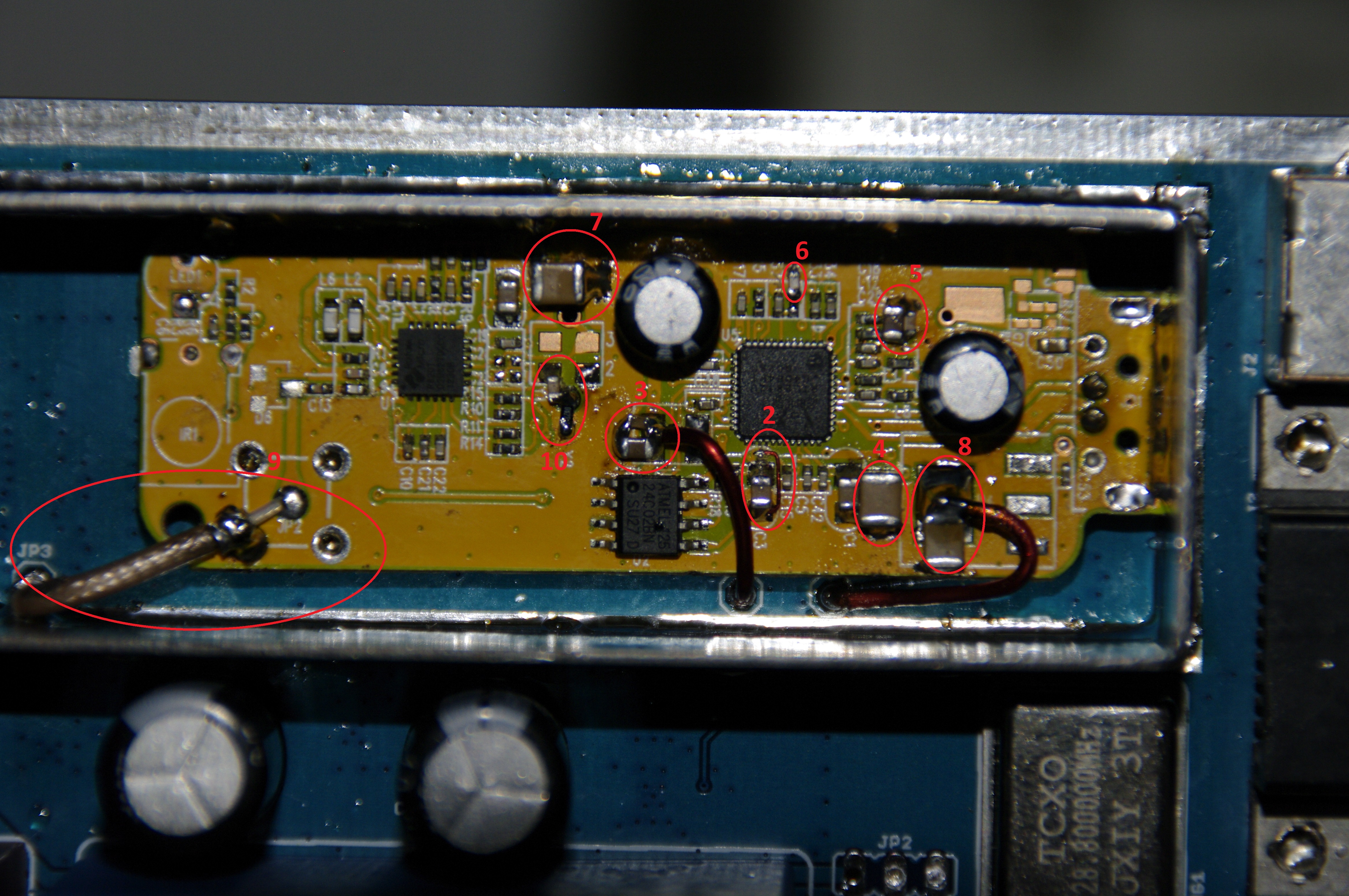
For integration in the assembly presented here, some modifications have to be done on a DVB-T R820T dongle (some mods are tricky : be sure you know what you do) :
- Remove USB connector, the LED, the IR sensor, the inductor L7 (4R7), the transil diode D6, the crystal Y2 and its 2 capacitors, the regulator U4 (3,3V),
- Cut the track from pin 27 of the RTL2832 and connect that pin27 to ground,
- Add 10nF + 22uF on 1,2V in place of L7 and inject 1,2V from JP6 of the PCB,
- Add 47uF close to C1,
- Add 10nF + 22uF on the track just before L4,
- Add 10nF on the track just before L5,
- Add 47uF + 10nF close to C2,
- Add 47uF in place of U4 and inject 3,3V from JP5 of the PCB,
- Inject the output of the LNA from JP3 using a small coaxial in JP2 of the dongle,
- Inject USB signals from the PCB in place of the USB connector of the dongle,
- Add the following circuit to inject the 28,8Mhz in the tuner R820T :

The PCB is designed so that JP4 (28.8 MHz), and JP1 (USB) fall in front the R820T dongle pads. The easiest way is to solder some resistors’ legs on the three points of the PCB and then set up the dongle into the shielding box by ensuring that the resistors’ legs fit directly into the corresponding pads of the dongle. It is therefore recommended to make all other mods before. Once in place, it only remains to solder the ground plane of the dongle to the shielding case on two edges.
Here are the caractistics of the LNA after building the prototype (S11 at the input of the LNA using a 50ohms load at the output in place of the dongle) :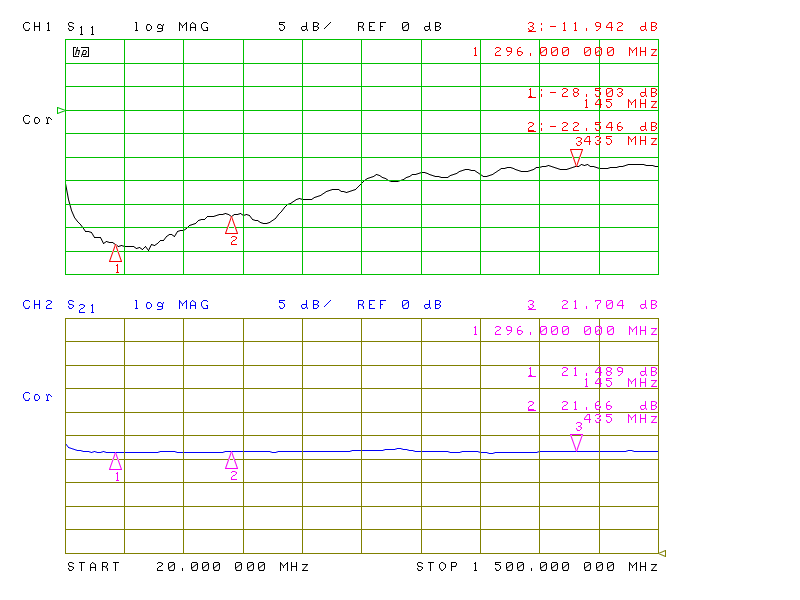
The S11 parameter is almost the same when replacing the load used for the measurement by the DVB-T dongle.
Usage as SDR
This assembly may also be used with any SDR software compliant RTL2832. The interest in this case is to take advantage of the optimizations of the dongle for a better reception quality (less spurs mainly, the reception gain in addition, frequency stability, noise floor slightly better).
If this arrangement is made just for this purpose, in this case, it is not necessary to wire the entire 28V supply portion to the noise source.
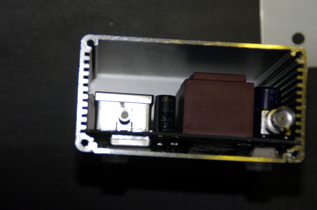
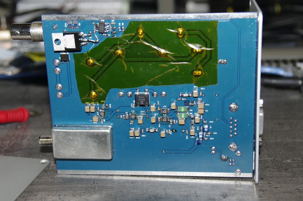
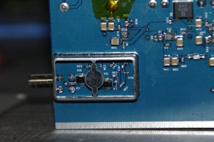
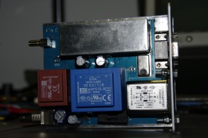
Some pictures of the prototype
Please note, the photos presented here are those of my prototype so there are elements that may be different from the version of PCB proposed here.
 |
 |
 |
 |
WARNING !!!!
There is high voltage in this assembly that can therefore be dangerous to handle on. I CAN IN ANYWAY BE RESPONSABLE FOR THE USE THAT WILL BE DONE OF THE ASSEMBLY : THE READER HAS TO TAKE ALL NECESSARY PRECAUTIONS FOR ITS OWN SECURITY.
For information on my prototype I protected all the high voltage section with KAPTON and I made sure to cut the components’ legs enough to prevent the KAPTON to be torn.
Cadsoft EAGLE Files
Bill of Materials
| Parts | Value | Qty | Package | Manufacturer | Description | FARNELL | RS | MOUSER |
| R1 | 16.5k | 1 | 0603 | 2059425 | 754-RR0816P-1652D22C | |||
| R2 | 56k | 1 | 0603 | 2447399 | ||||
| R3 | 12k | 1 | 0603 | 9238611 | ||||
| R4 | 100k | 1 | 0603 | 2447226 | ||||
| R5 | 4.7k | 1 | 0603 | 2447385 | ||||
| R6 | 84.5 | 1 | 0603 | 2303053 | ||||
| R7 | 1.8k | 1 | 0603 | 2447283 | ||||
| R8, R9 | 0.05 | 2 | 2512 | 1100065 | 756-LRMAM2512R05FT4 | |||
| R10 | 49.9k | 1 | 0603 | 2447380 | ||||
| R11 | 71.5 | 1 | 0603 | 1170672 | 667-ERJ-3EKF71R5V | |||
| R12, R13 | 97.6 | 2 | 0603 | 2326678 | 667-ERJ-3EKF97R6V | |||
| R15 | 6.8k | 1 | 0603 | 2447427 | ||||
| R16 | 470 | 1 | 0603 | 2447374 | ||||
| C1, C4, C8, C13, C23, C24, C25, C30, C33, C35, C37, C42, C44, C46, C53, C55, C56, C58 | 10nF | 18 | 0603 | 1759102 | 77-VJ0603Y103KXACBC | |||
| C2, C21, C39 | 100nF | 3 | 0603 | 432210 | ||||
| C3, C5, C26 | 22uF | 3 | 0805 | 10V CAPACITOR | 2346921 | |||
| C6, C15, C16, C17, C19, C20, C27, C28, C29, C40, C41, C43, C45, C47, C54, C57 | 47uF | 16 | 1210 | 16V CAPACITOR | 1828819 | 81-GRM32ER61C476KE5L | ||
| C7 | 330uF | 1 | E5-13 | 100V POLARIZED CAPACITOR | 1907145 | |||
| C9 | 680uF | 1 | E5-10.5 | 35V POLARIZED CAPACITOR | 1800669 | |||
| C12, C14 | 2200uF | 2 | E5-10.5 | 16V POLARIZED CAPACITOR | 2346569 | |||
| C22, C34, C36 | 100pF | 3 | 0603 | 1759066 | ||||
| C31, C32, C38 | 1uF | 3 | 0603 | 1907343 | ||||
| C48 | 12pF | 1 | 0603 | 1759054 | ||||
| C49 | 15pF | 1 | 0603 | 1759055 | ||||
| C50 | 220pF | 1 | 0603 | 1759070 | ||||
| C51 | 270pF | 1 | 0603 | 1759072 | ||||
| C52 | 120pF | 1 | 0603 | 2496885 | ||||
| F2, F3, F4, F5 | NFE61PT102E1H9L | 4 | MURATA | EMI Filter | 9528202 | 81-NFE61PT102E1H9L | ||
| L1 | 744232090 | 1 | 1206 | WURTH | 1636474 | 500-3032 | ||
| L2, L3 | 820nH | 2 | 0805 | COILCRAFT | 0805CS-821XJLB | 2286433 | 994-0805CS-821XJLB | |
| L4 | MMZ1608B301C | 1 | 0603 | TDK | EMI Suppression Ferrite Beads | 1669686 | ||
| L5 | 270nH | 1 | 1210 | COILCRAFT | 1008CS-271XGLC | 2286664 | 994-1008CS-271XGLB | |
| L6 | 470nH | 1 | 1210 | COILCRAFT | 1008CS-471XJLB | 2286707 | 994-1008CS-471XJLB | |
| L7 | 680nH | 1 | 1210 | COILCRAFT | 1008CS-681XGLB | 2286670 | 994-1008CS-681XGLB | |
| IC1, IC6 | MGA-30889-BLKG | 2 | SOT89 | AVAGO | 1865178 | 630-MGA-30889-BLKG | ||
| IC2 | TL783CKCSE | 1 | TO-220 | TEXAS | 1703396 | |||
| IC3, IC4, IC5, IC7 | LT3042MSE | 4 | MSOP10 | LINEAR | Ultra low noise positive regulator | 2475652 | ||
| T1 | ZVP4424G | 1 | SOT-223 | DIODES INC. | Transistor P-Channel | 9526757 | ||
| T2 | 2N2222 | 1 | TO92 | NPN Transistror | 1611371 | |||
| B1 | MB6S | 1 | Bridge Rectifier | 1861519 | ||||
| B2 | DBS102G | 1 | Bridge Rectifier 1A | 1861404 | 583-DB103S-T | |||
| TR1 | 44229 | 1 | EI42-1 | MYRRA | Transformer 6V 5VA | 1689079 | 732-0540 | |
| TR2 | 44166 | 1 | EI30-2 | MYRRA | Transformer 2x15v 2.8VA | 1214590 | 173-9816 | |
| QG1 | 1 | XO-14 | TCXO 28,8MHz 0,5ppm (EBAY) | |||||
| J1 | FN9226-1-02 | 1 | SCHAFFNER | IEC Filter 1A | 2449537 | 631-FN9226-1-02 | ||
| J2 | 1 | FCI | USB Connector type B | 1097897 | ||||
| J3 | 5747844-5 | 1 | TE / AMP | SUB-D 9 | 1653995 | |||
| J4 | B6252HA-NPP3G-50 | 1 | AMPHENOL | BNC right angle |
1076293 | |||
| J5 | 73251-2200 | 1 | FEMALE SMA CONNECTOR | 2293854 | 800-6936 | |||
| SH1 | 403.16 | 1 | OKW | 237-2751 | ||||
| SH2 | MS355-10 | 1 | 826-6807 | |||||
| SH3 | 1 | HAMMOND | 4272900 | 546-1455N1201 |

 Français